Electronics Design (WEEK 6 )
Individual assignmentRead a microcontroller data sheet program your board to do something, with as many different programming languages and programming environments as possible
Learning outcomesSelect and use software for circuit board design
Demonstrate workflows used in circuit board design
PCB DesigningI used EAGLE software for designing echo hello - world circuits. its my first experience in design circuit. downloaded the file from AUTODESK website and installed.
How to start with EAGLE?Double click the EAGLE icon and open it. Select 'new' from file to start a new project and name it. This will work as directory. Then again click and open ' SCHEMATIC' from file.Adding FABLAB Library
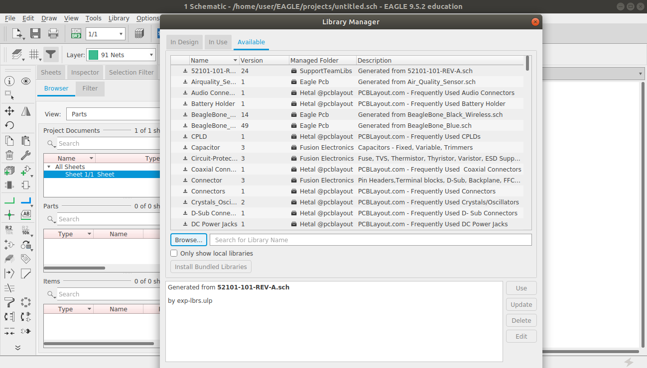
Now we want to update the FABLAB parts library by going through LIBRARY MANAGER. Firstly we need to download the file from the link here
How to add parts/ components?Click 'ADD' button from tool bar. The click 'open library MANAGER'. browse and add ' fab.lbr' file as mentioned above. now click "update all" from 'LIBRARY' to confirm the library addition. Now you will able to add parts typically seen in fablabs.
For completing the assignment we only need following components

        •         ATtiny44 x 1
        •         XTAL 20HZ x 1
        •         Resistor 10K x 2
        •         Resistor 499ohm x 1
        •         Capacitor 10uf x 1
        •         Push button x 1
        •         ISP header (3x2 pin) x 1
        •         FTDI header (1x6 pin) x1
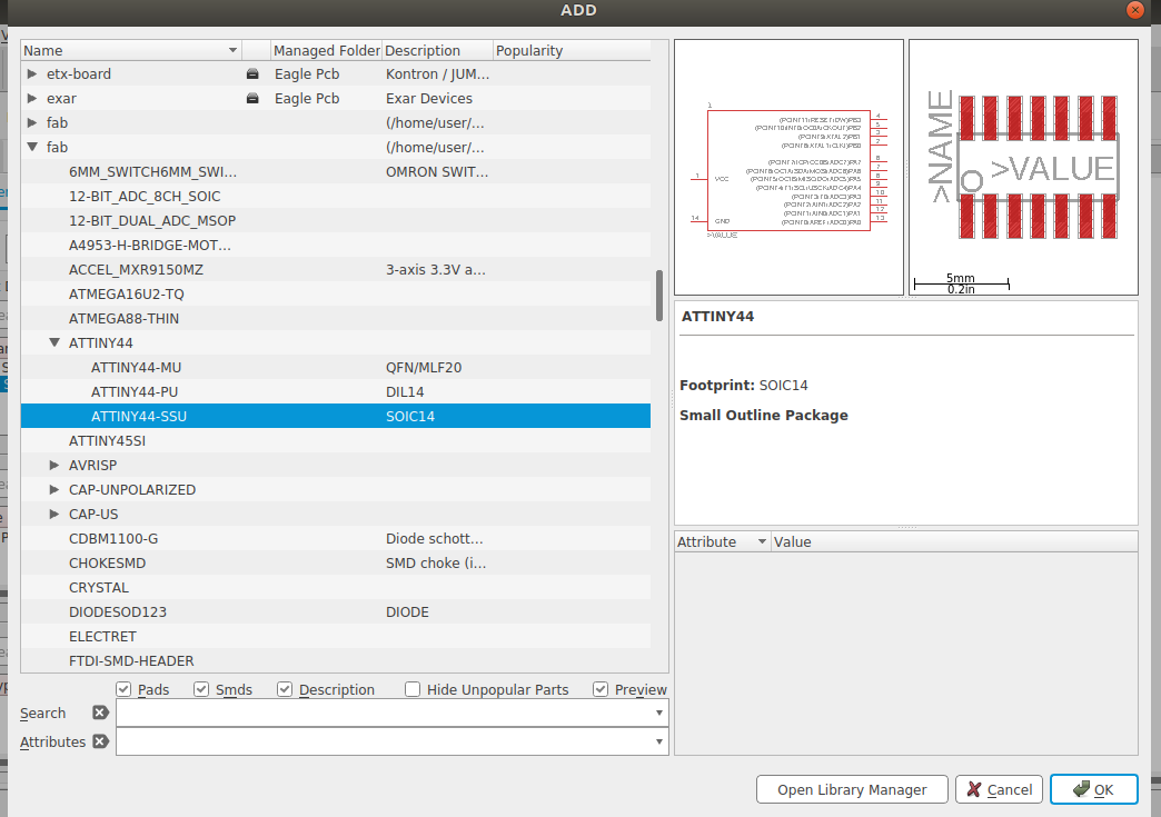
Adding ATtiny44
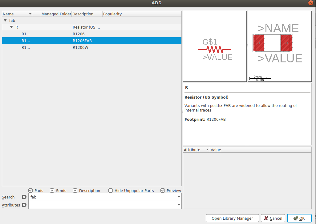
Adding Resistor
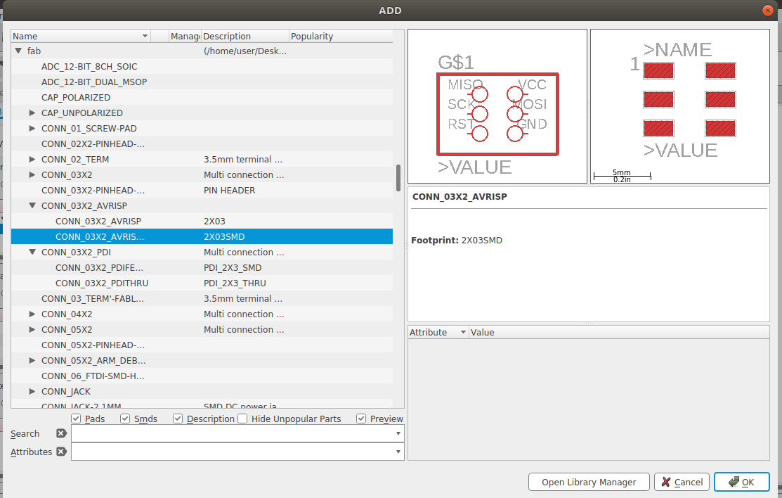
Adding ISP header
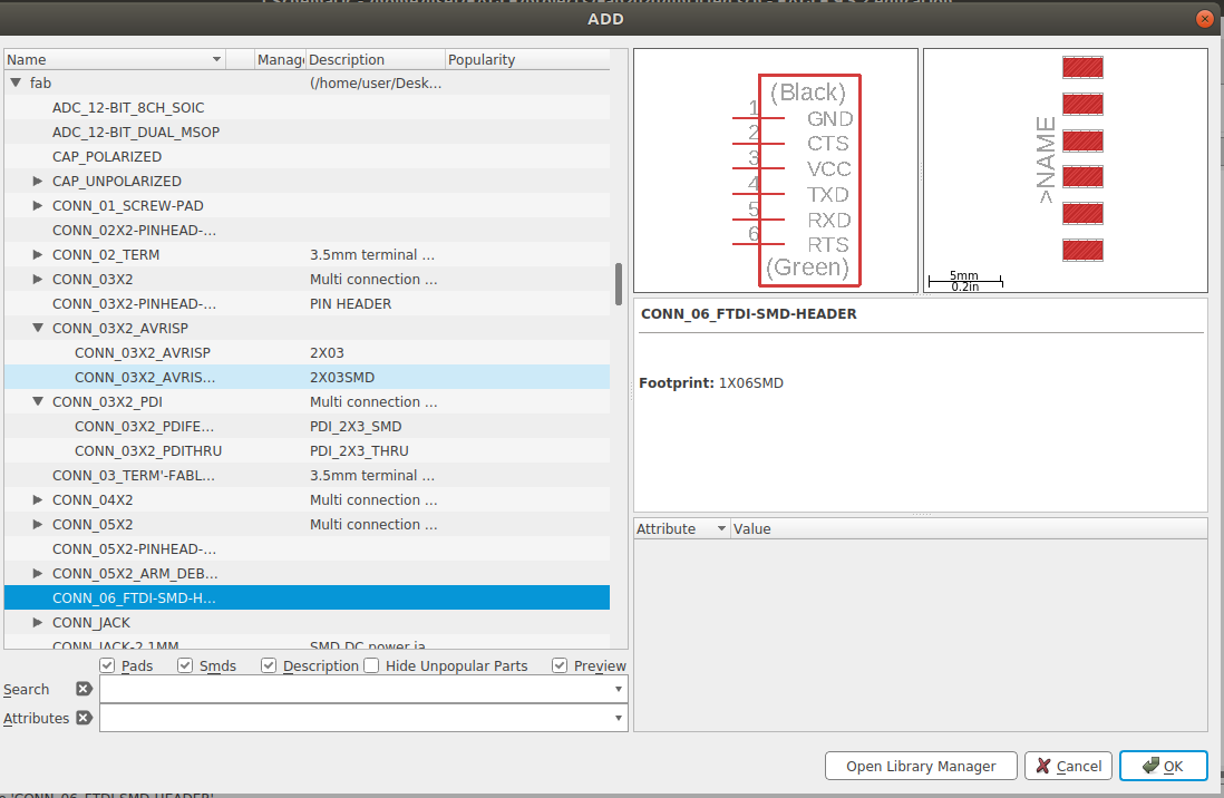
Adding FTDI header
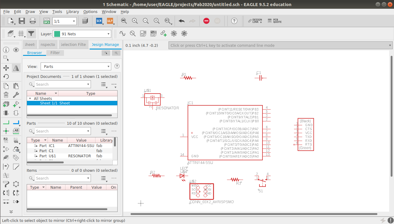
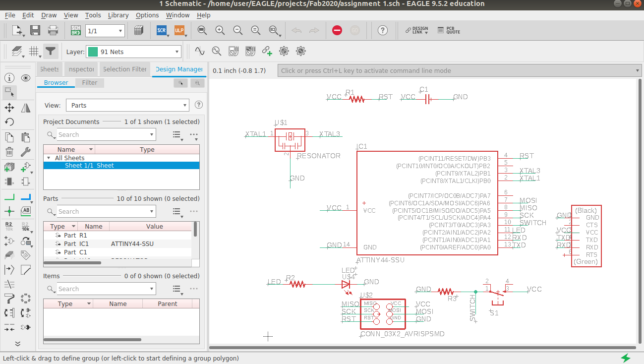
Place and arrange all componenets on worksheet.
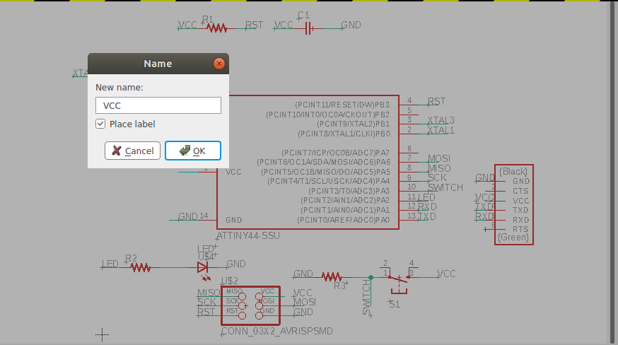
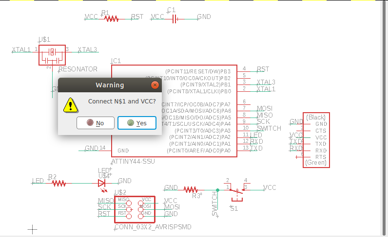
 Now for drawing connections use NET tool and NAME tool together.
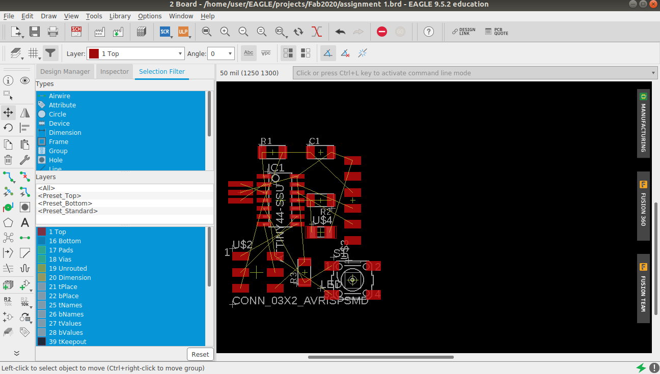
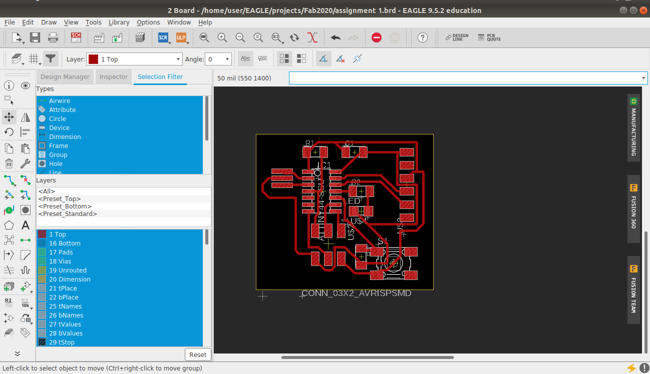
After completing the connections click 'Generate /switch to board' Tool. A new window will be opened and all components with connecions will be seen there. Move all components as close as possible around the IC chip
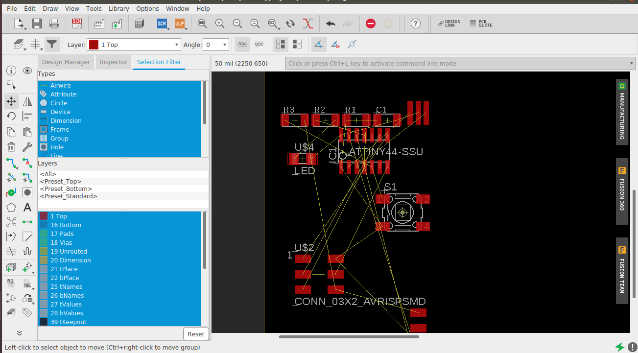
After rearranging
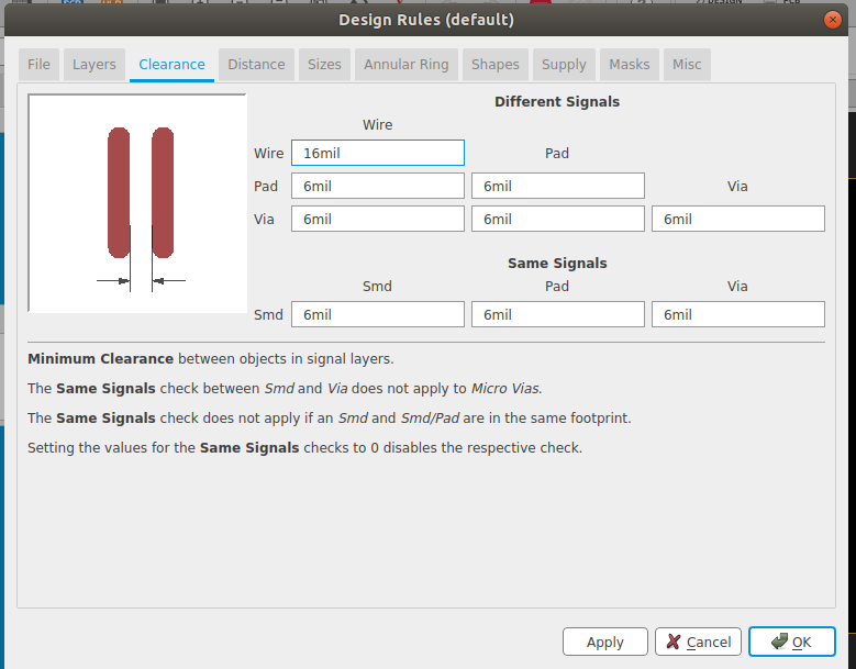
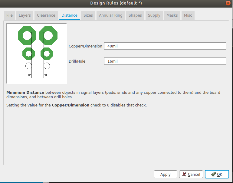
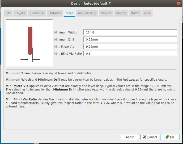
Before going to autoroute . we need to go to 'design rule' from 'EDIT' and change value from 6 mills to 16 mills.Because we are using 1/64 trace tool for PCB milling
Now click 'Autorouter' button on the tool bar, autoroute main setup window will be poped up. Give option 'Auto' for 'Top' seen in preferred directions window and 'N/A' for the rest.
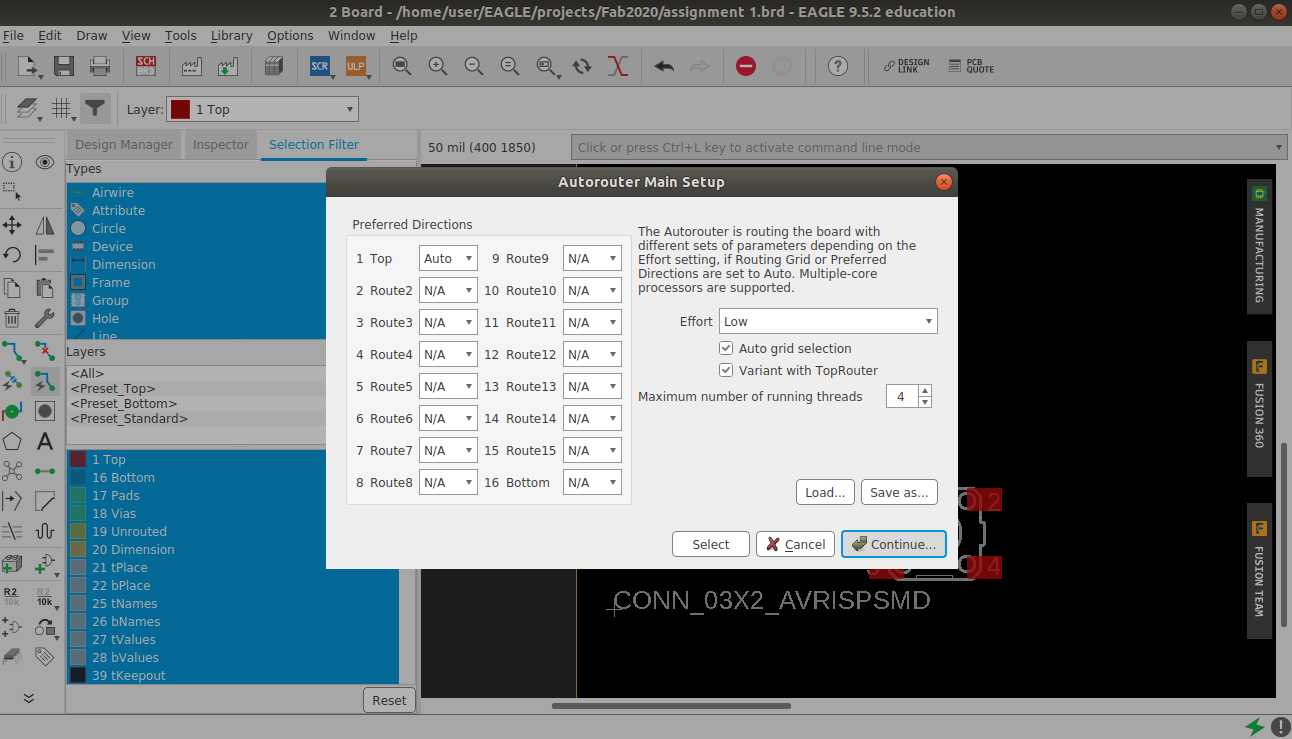
Click ' Continue ' after some seconds the 5 best optimized routing variants will be shown. We need atleast one 100% optimization completed route.
If not getting 100% rearrange the components by using 'ripup' tool and go for auto routing. Some times we may need to do manual connection using 'route airwire'. I tried many times to get an 100% optimized route.
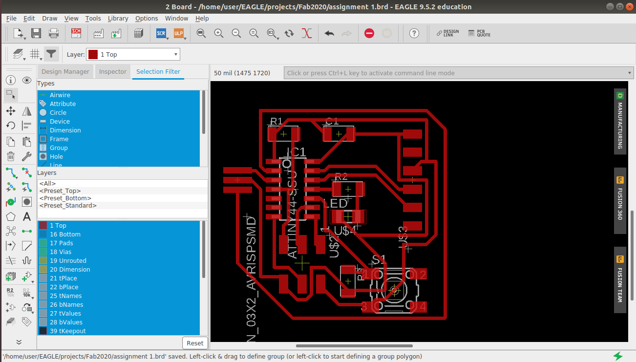
I noticed that one of tracing line is taking longer distance for connection. I used ripup and route airware to recify the imperfection.
Next task is to export the trace image. For that I opened layers setting, then hide all layers expect dimension layer.
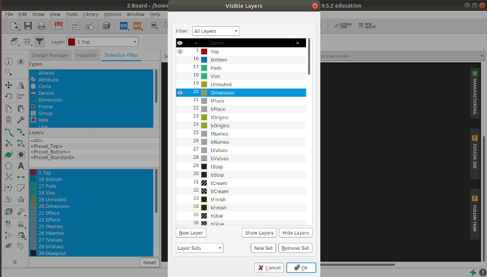
Now export the image by giving following settings
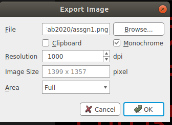
My trace after exporting.
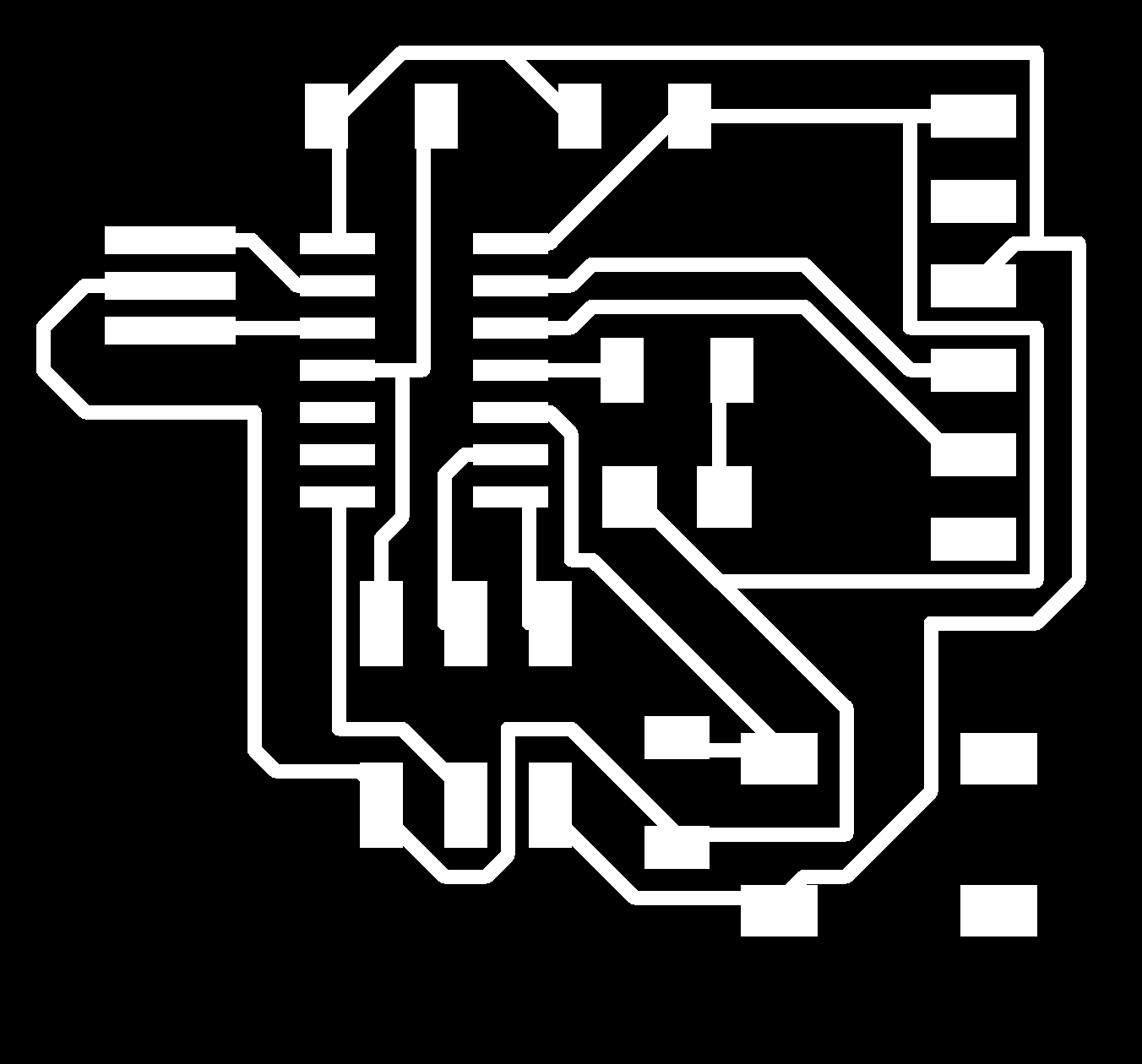
Then I used PCB Milling machine to milling out the board and soldered all components. I referred my previous lession milling and soldering for completing this task. Referred Week4 Electronic Production
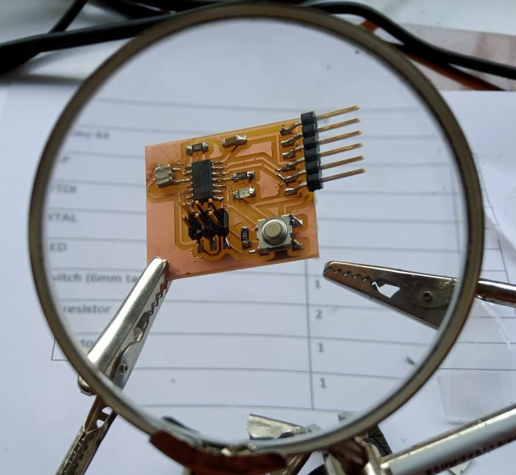
TESTING
Using Arduino IDE i programmed the board
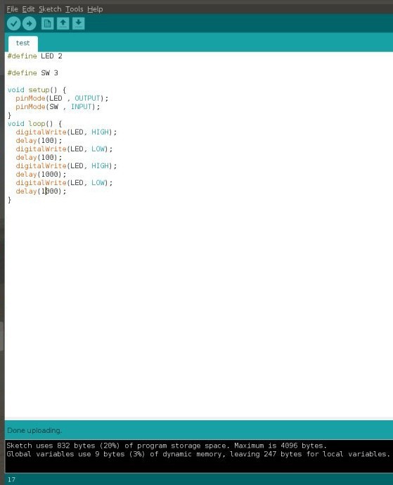
Successfuly tested
With the help of my instructor i programmed a simple blink program using Arduino IDE.
Group Assignmet
Link to week6- electronics design- Group assignment
Click Here